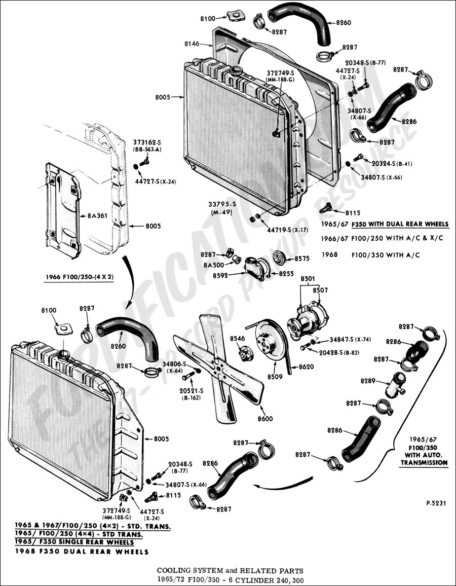
1999 Ford F250 5 4 Trottle Body Cooling System Diagram

Diagram Ford F 250 Cooling System Diagram Mydiagram Online Remove the ten ignition coils. 26. page 6 1999 f super duty 250 550 workshop manual 28. disconnect the cylinder head temperature sensor. 29. remove the water thermostat and housing. 30. remove the bolts, the upper intake manifold and the intake manifold gaskets (9439). discard the intake manifold gaskets. The coolant system in the ford 5.4 includes several key components, including the radiator, water pump, thermostat, coolant reservoir, and various hoses. these components work together to circulate coolant throughout the engine, cooling it down and preventing it from overheating. the coolant begins its journey in the radiator, where it is.

Diagram Ford F 250 Cooling System Diagram Mydiagram Online 1997 2003 f150 1999 5.4 f250 ld pcv valve "y" diagram where does this go? pics enclosed 95289i have a 1999 f250 5.4 ld. i just replaced the pcv valve hose from back of intake. now i don't remember how it attaches to the y and if this yellow vacuum hose is connected to the y . please look at my pics and explain . Starting in early 2000’s, many car makers including ford started installing fly by wire electronic throttle bodies. in those vehicles, the “gas” pedal isn’t connected to the throttle body by a cable. the pedal simply provides an electronic signal, telling the throttle body how much acceleration you’re requesting. On many engines i've seen coolant is circulated through the idle air control valve and the throttle body. one such example is the mazda 2l 4 cylinder fs used in the 626. the iac is ecu controlled, and there is a coolant temperature sensor, so what would be the purpose of running coolant through the iac? you can see in this diagram for example. Intermittent stall with a p0505 .low or high idle .in this video i will show you how to replace the throttle body on a 2006 ford f350 with a 5.4 liter engine.

The Ultimate Guide To Understanding Ford 5 4 Coolant Flow Diagram On many engines i've seen coolant is circulated through the idle air control valve and the throttle body. one such example is the mazda 2l 4 cylinder fs used in the 626. the iac is ecu controlled, and there is a coolant temperature sensor, so what would be the purpose of running coolant through the iac? you can see in this diagram for example. Intermittent stall with a p0505 .low or high idle .in this video i will show you how to replace the throttle body on a 2006 ford f350 with a 5.4 liter engine. The 5.4 triton vacuum hose diagram can be found in most ford service manuals. it is a simple diagram that shows the various hoses and connections that make up the 5.4 triton engine’s vacuum system. the diagram is essential for anyone who needs to work on the engine, as it helps to ensure that all of the hoses are properly connected. Ford tech tips v2 | n2 2020 5 throttle body and throttle pedal diagnostics it’s a hardware and software strategy delivering engine torque output via throttle angle. based on driver intent, torque based electronic throttle uses a throttle pedal position sensor. gen ii is a drive by wire system eliminating the idle air control system.

1999 Ford F250 Engine Diagram The 5.4 triton vacuum hose diagram can be found in most ford service manuals. it is a simple diagram that shows the various hoses and connections that make up the 5.4 triton engine’s vacuum system. the diagram is essential for anyone who needs to work on the engine, as it helps to ensure that all of the hoses are properly connected. Ford tech tips v2 | n2 2020 5 throttle body and throttle pedal diagnostics it’s a hardware and software strategy delivering engine torque output via throttle angle. based on driver intent, torque based electronic throttle uses a throttle pedal position sensor. gen ii is a drive by wire system eliminating the idle air control system.

I Need A Diagram Photo Schematic Of 1999 Ford F 150 Tritan 5 4 Engine

Comments are closed.