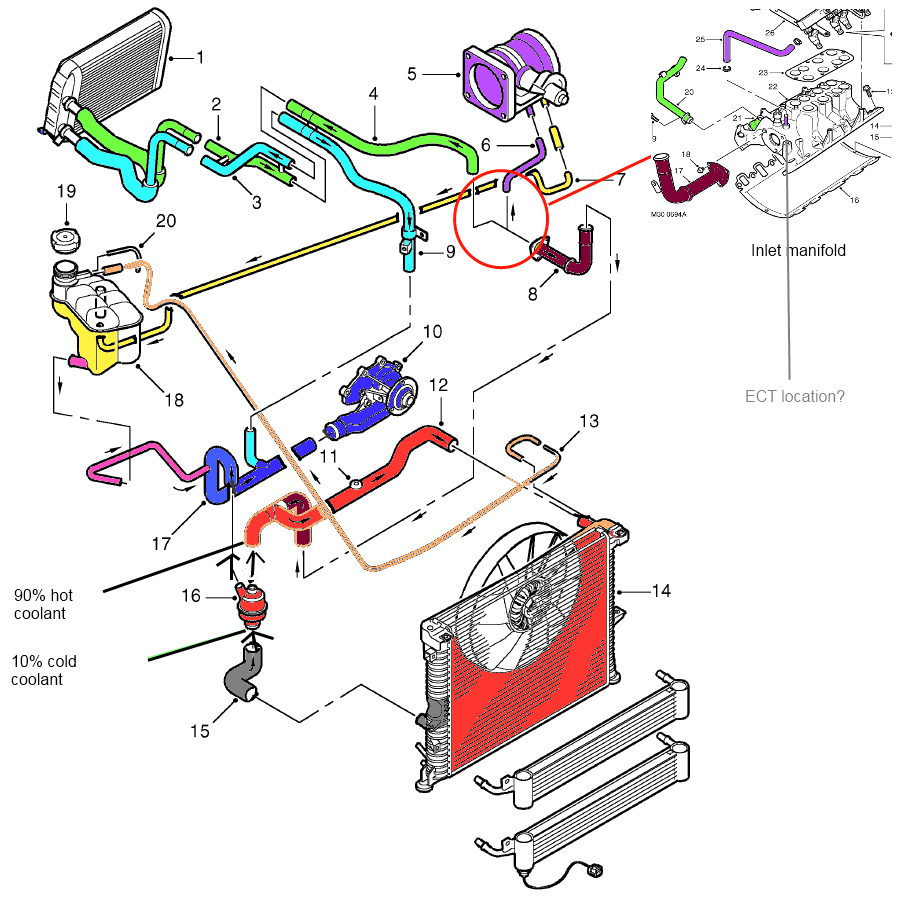
2004 Ford 6 0 Engine Cooling System Parts Diagram

Visual Guide To Cooling System Parts Diagram For 2004 Ford 6о The cooling system in a 2004 ford 6.0 engine consists of several key parts that work together to control engine temperature and prevent overheating. these parts include the radiator, water pump, thermostat, fan clutch, coolant hoses, and the coolant reservoir. each component plays a vital role in maintaining the engine’s operating temperature. 6 piston cooling tubes. 8. high pressure hydraulic pump oil reservoir. • this reservoir (below oil cooler) has a constant supply of oil for the pressure hydraulic oil pump. it has an approximate capacity of 0.9 l (0.95 qt). 303 01c 11 engine — 6.0l diesel 303 01c 11 description and operation (continued) 2005 f 250, 350, 450, 550 super duty.

Q A Ford 6 0 Powerstroke Coolant Flow Hose Diagrams 2004 system wiring diagrams ford pickup f350 super duty cooling fan 6.0l 2004 ford pickup f250 super duty engine performance circuit (1 of 5) 2004 ford. This guide will acquaint you with the 6.0l power stroke diesel engine. it provides recommendations on engine care and operating procedures. for complete vehicle information, also refer to the owner’s guide included with the vehicle. page 3 introduction overpressurization and the risk of fuel expulsion and fires. 2.0 cooling system basics fig. 2.1 reference: 6.0 power stroke 2003.25 “f” series super duty features descriptions unique service procedures and general diagnostics the diagram above shows the 3 circuits that the engine coolant takes from the water pump. there is a circuit for each side of the engine and one to the oil cooler egr cooler. Here is a direct link to the cooling system flow chart. page 17: cooling system. thanks alot! 6.0l power stroke diesel coolant flow diagram i need to flush out my block and heater core as part of my rebuild resulting from a blown oil cooler. i know i have seen a diagram for the coolant flow on this site before but i cant seem to find it now.

Ford 6 0 Cooling System Diagram 2.0 cooling system basics fig. 2.1 reference: 6.0 power stroke 2003.25 “f” series super duty features descriptions unique service procedures and general diagnostics the diagram above shows the 3 circuits that the engine coolant takes from the water pump. there is a circuit for each side of the engine and one to the oil cooler egr cooler. Here is a direct link to the cooling system flow chart. page 17: cooling system. thanks alot! 6.0l power stroke diesel coolant flow diagram i need to flush out my block and heater core as part of my rebuild resulting from a blown oil cooler. i know i have seen a diagram for the coolant flow on this site before but i cant seem to find it now. During the 2003 model year, ford introduced the 6.0 powerstroke diesel. based on the navistar international vt365, this engine featured 4 valves per cylinder, a variable geometry turbo (vgt) turbo, and updated fuel system. the 6.0 was discontinued in super duty pickups after 2007, but continued production in the e series van through 2010. Cooling system flow diagram. for a 04 6.0? 04 f250 crew cab long bed 6.0, 5.5" lift, 35' toyo, airaid intake, banks 4" turbo back w cat, edge juice w attitude, autometer gauges (coolant, oil, trans temp),pulling 2006 30' ragen 5th wheel toyhauler 10,000 lbs loaded with quads. i run stock tune while towing.

6 0 Powerstroke Coolant Flow Diagram During the 2003 model year, ford introduced the 6.0 powerstroke diesel. based on the navistar international vt365, this engine featured 4 valves per cylinder, a variable geometry turbo (vgt) turbo, and updated fuel system. the 6.0 was discontinued in super duty pickups after 2007, but continued production in the e series van through 2010. Cooling system flow diagram. for a 04 6.0? 04 f250 crew cab long bed 6.0, 5.5" lift, 35' toyo, airaid intake, banks 4" turbo back w cat, edge juice w attitude, autometer gauges (coolant, oil, trans temp),pulling 2006 30' ragen 5th wheel toyhauler 10,000 lbs loaded with quads. i run stock tune while towing.

Comments are closed.