Cooling Fan To Temp Sensor Wiring Diagram

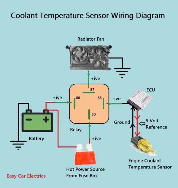
Coolant Temperature Sensor Wiring Diagram General Wiring Diag This video shows how to easily wire an electric radiator fan circuit into any car. this fan wiring diagram includes a fan relay, a temperature switch, and a. 3 wire coolant temperature sensor wiring diagram. the two wires, a “5 volt reference”, and a “ground wire” go to the ecu, and the third wire “earth 1 wire for temp gauge” goes to the cluster mounted temperature gauge by providing an earth link to the temperature gauge. in three wire coolant temp sensors, the ecu does not control the.

1 2 3 Wire Coolant Temperature Sensor Wiring Diagram Optionally, a single high current relay could be used to control both fans. the supplied diagram below using dual relays with a single temp sensor is both the most reliable and easiest method we've found for wiring dual fans. it uses our 40 amp electric relay kit and electric fan sensor. the relay isolates the high amp load of the fan circuit. How to wire electric radiator cooling fans using the alloy works relay and temperature switch kit. this kit can be purchased here: alloyworksplus. With dual cooling fans, there are two methods for wiring up the relay kit. this is based on the draw from the fans, if the fans are larger and draw more than 15 amps each, it's recommended to install a second relay kit as shown below. for smaller fans, both fans can be connected to a single relay as shown above, and the proper fuse should be. Install the temperature controlled sending unit in one of the cooling passage ports on your intake manifold, making sure to use a high temperature thread sealant to prevent leaks. the sending unit.
.jpg)
Inside A Car вђ Coolant Temperature Sensors With dual cooling fans, there are two methods for wiring up the relay kit. this is based on the draw from the fans, if the fans are larger and draw more than 15 amps each, it's recommended to install a second relay kit as shown below. for smaller fans, both fans can be connected to a single relay as shown above, and the proper fuse should be. Install the temperature controlled sending unit in one of the cooling passage ports on your intake manifold, making sure to use a high temperature thread sealant to prevent leaks. the sending unit. The aux fan in this engine has a fan connector with 3 wires in it, blue 12 volts, brown ground, and a thin black wire that comes from the dme to supply pwm signals (square waves) to control the fan speed. the speed is controlled by the dme with inputs from the temp sensor in the lower hose as well as the pressure switch, the hvac panel. The engine operating temperature will still be governed by the coolant thermostat. the peak temperature may drop by about ~7° when stopped, or in stop n go traffic. a manual switch could also be tapped into this same circuit. heres a diagram of the cooling fan circuit: i added the arrows to indicate current flow, from positive to negative.

Engine Coolant Temperature Sensor Diagram The aux fan in this engine has a fan connector with 3 wires in it, blue 12 volts, brown ground, and a thin black wire that comes from the dme to supply pwm signals (square waves) to control the fan speed. the speed is controlled by the dme with inputs from the temp sensor in the lower hose as well as the pressure switch, the hvac panel. The engine operating temperature will still be governed by the coolant thermostat. the peak temperature may drop by about ~7° when stopped, or in stop n go traffic. a manual switch could also be tapped into this same circuit. heres a diagram of the cooling fan circuit: i added the arrows to indicate current flow, from positive to negative.

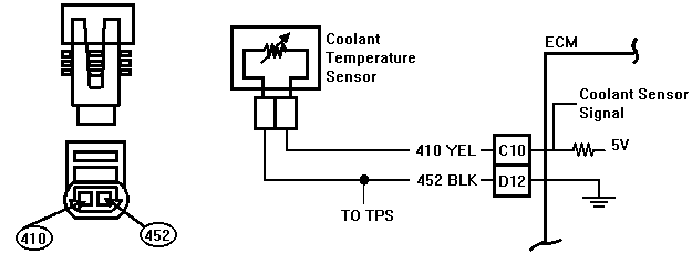
Code 15 Coolant Temperature Sensor Circuit

Comments are closed.