Cooling Tower Diagram Water Distribution

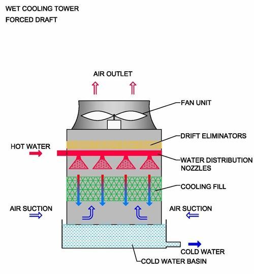
Cooling Tower Diagram A Go To Guide To Learn About Their Function Condenser water return pipework [1] the cooling tower return pipework is installed to transport the warm water from the condenser side of the water cooled chiller to the cooling tower, with the flow being provided by the condenser water pumps that are installed on the supply side of the tower [tower to chiller] to move the water around the system. A cooling tower flow diagram is a visual representation of the flow of water and air in a cooling tower system. it provides a clear understanding of how the cooling tower operates and helps in identifying potential issues or inefficiencies in the system. there are several benefits of using a cooling tower flow diagram.

Cooling Towers Explained How Does A Cooling Tower Work In a cross flow cooling tower, the hot water basin is used to distribute the warm return water flow uniformly over the tower fill (see figure 6). in a counter flow cooling tower, water sprays are used to distribute the warm water (see figure 8). the fan deck supports the motor and fan of the water spray system. An industrial process is pumped up to the top of the cooling tower where the water distribution system is. the water then gets distributed by cooling tower nozzles to the wet deck. at the same time, air is being drawn through the air inlet louvers forcing water to evaporate. evaporation causes the heat to be removed from the make up water. the. By fans into the cooling tower and up through the flow of falling water in the cooling tower. drift eliminators are installed to prevent water entrained in the air from leaving the system. 1.3.3 induced draft towers. the term “induced draft” denotes that air is drawn by fans through the flow of falling water and up and out of the cooling tower. Water distribution system. water must be distributed uniformly throughout the cooling tower’s fill media using the water distribution system. distribution basins, nozzles, and pipes are usually included. water is dispersed or sprayed over the fill medium at the top of the tower after being pumped from the tower basin.

A Sketch Of Water Distribution In A Cooling Tower In A Modern 1000 Mw By fans into the cooling tower and up through the flow of falling water in the cooling tower. drift eliminators are installed to prevent water entrained in the air from leaving the system. 1.3.3 induced draft towers. the term “induced draft” denotes that air is drawn by fans through the flow of falling water and up and out of the cooling tower. Water distribution system. water must be distributed uniformly throughout the cooling tower’s fill media using the water distribution system. distribution basins, nozzles, and pipes are usually included. water is dispersed or sprayed over the fill medium at the top of the tower after being pumped from the tower basin. Design capacity – 430.0 gpm design head – 47.0 feet motor size – 10 hp. less than anticipated pump headthe pump point shift has increased flow. over design to the order of 45%. cavitational and or tower vortex can occur unless. corrective measures are applied.the pump impeller diameter could, and should be cut down. One of the key components of a cooling tower is the water distribution system. this system distributes water evenly across the cooling tower, allowing for effective heat transfer. by understanding the flow diagram of the water distribution system, it becomes possible to identify any areas where the distribution may be uneven or inadequate.

Comments are closed.