Goodman 1 5 Straight Cool Handler Wiring Diagram

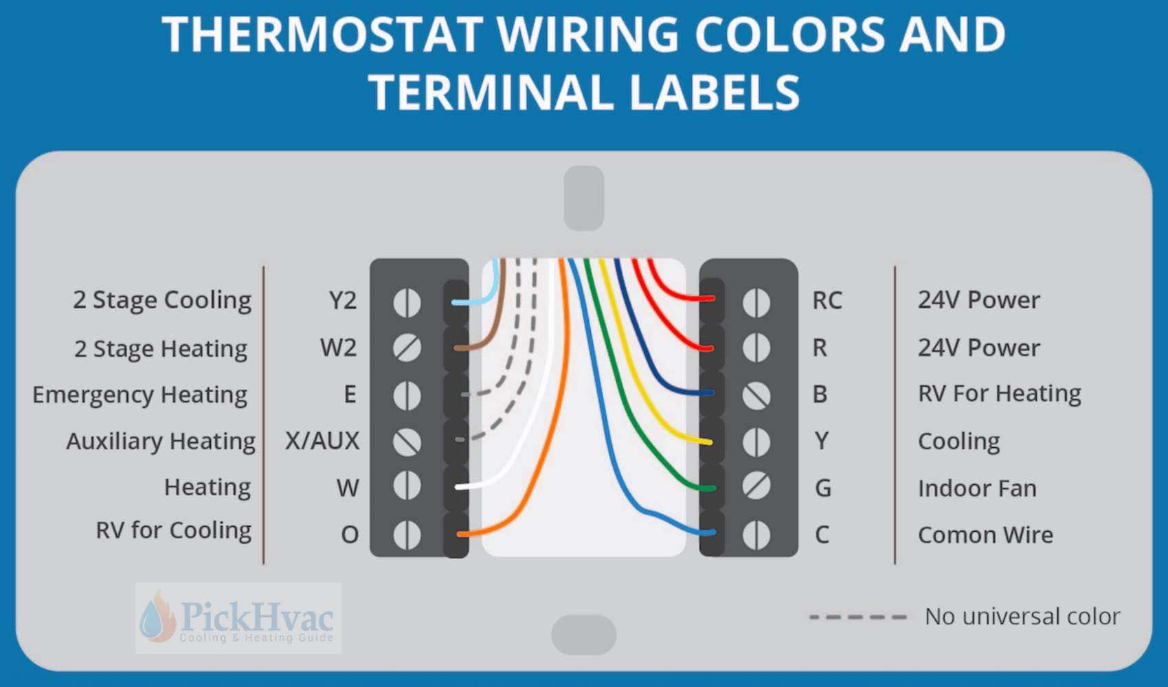
Straight Cool Air Handler Wiring Diagram 3. unsweat the access fitting on the tailpiece internal wiring a diagram of the internal wiring of this unit is located under the 4. remove the check piston to verify it is correct and then electrical box cover. if any of the original wire as supplied with replace the piston. page 6: maintenance maintenance ceiling mount unit room thermostat w. Strip the ends of the wires. use a wire stripper to remove about 1 2 inch of insulation from the ends of the wires. 4. connect the wires to the terminals. the wires from the air handler will be connected to the terminals in the junction box. the colors of the wires will correspond to the colors of the terminals. 5.

Goodman Air Handler Wiring Diagrams Page 21: wiring diagrams 21 wiring diagrams high voltage! disconnect all power before servicing. warning multiple power sources may be present. failure to do so may cause property damage, personal injury or death. aruf**14** arpt**14** 208 240 terminal block shown see notes 2 & 6 volts equipment ground for 50hz models only use copper wire. 4 condensing unit specifications gsc130 (42 60) 5 cooling performance data gsc130601cb. 6 wiring diagrams gsc 130 (18 60)1. download this manual. gsc13 seer condensing units. •. refer to service manual rs6100004 for installation, operation, and troubleshooting information. •. all safety information must be followed as provided in the. Wiring is subject to change. always refer to the wiring diagram on the unit for the most up to date wiring. ⚠ warning high voltage: disconnect all power before servicing or installing this unit. multiple power sources may be present. failure to do so may cause property damage, personal injury, or death. ⚡ acnf wiring diagram (no electric heat). The wiring diagram for a goodman air handler is a detailed representation of the electrical connections inside the unit. it shows each wire’s path and connection points, including color coded labels for easy identification. understanding how to read the diagram will enable you to trace the flow of electricity and diagnose any potential issues.

Comments are closed.