Problem With Interpreting Sap 2000 Shell Forces And Stresses Here Is The Solution Engineering

Problem With Interpreting Sap 2000 Shell Forces And Stressesо Problem with interpreting sap 2000 shell forces and stresses ? here is the solution. #engineering. Internal force in sap2000 are indentified with: normal forces: prefix f moments: prefix m shear forces: prefix v in sap2000 force we can show using local or global coordinate system. all calculation are based on global coordinate system, but we can see force and in some diferent coordinate system. in most situation we do not need to define new.

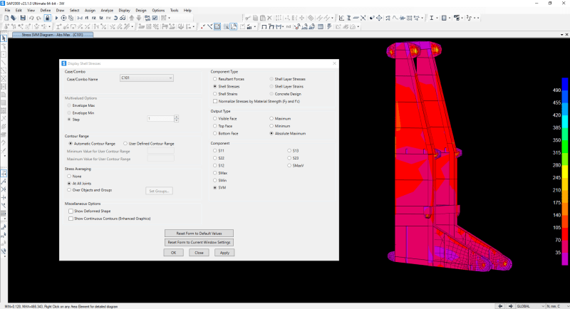
Sap2000 34 Concrete Shell Reinforcement Design Watch Learn Youtube 7 sep 22 03:50. regarding to von mises stress of shell in sap2000, when i run load combination with linear category, the von mises stress is normal value (see picture 1), but when i run load combination with envelope category,the von mises stress is seem equal zero (see picture 2). thanks in advance. replies continue below. Look at the moment and shears in the column or pile support. look at the geometry of the pile and punching perimeter. after that, it's just a hand calculation. however, the safe guys (if i remember correctly) try to use direct fem results in their punching calculations. Answer: yes, the shell stresses obtained using sap2000 may be compared directly to the allowable stress of the shell material, as this is the essence of allowable stress design (asd). shell stresses may be reviewed in tabular format through display > show tables > analysis results > element output > area output > table: element stresses area. To create this model, go to the file menu>new model and select the grid only option. under the cartesian tab, fill in the number of grid lines in the x direction (2), y direction (1) and z direction (2). the grid spacing is 2000 inches in the x direction, 288 inches in the y direction, and 72 inches in the z direction.

Display Shell Stresses Von Mises Stress Computers And Structures Answer: yes, the shell stresses obtained using sap2000 may be compared directly to the allowable stress of the shell material, as this is the essence of allowable stress design (asd). shell stresses may be reviewed in tabular format through display > show tables > analysis results > element output > area output > table: element stresses area. To create this model, go to the file menu>new model and select the grid only option. under the cartesian tab, fill in the number of grid lines in the x direction (2), y direction (1) and z direction (2). the grid spacing is 2000 inches in the x direction, 288 inches in the y direction, and 72 inches in the z direction. I don't understand why solid stresses (s11, s22, s33, s12, s13, s23) are reported for each joint of a solid (an eight node brick element). i suppose it is reported per solid, and the stresses correspond to its 6 positive negative faces. if we look at joint forces, each joint has 3 translational dof, instead of 6 values. When this check box is checked, sap2000 will display the model using color coded contours with distortions to show where the model is subject to the effects of the forces and stresses. note: shell element stresses (not forces) actually have different values at the top and bottom of the shell elements as a result of bending.

Comments are closed.