Wiring Diagram For Evaporative Cooler

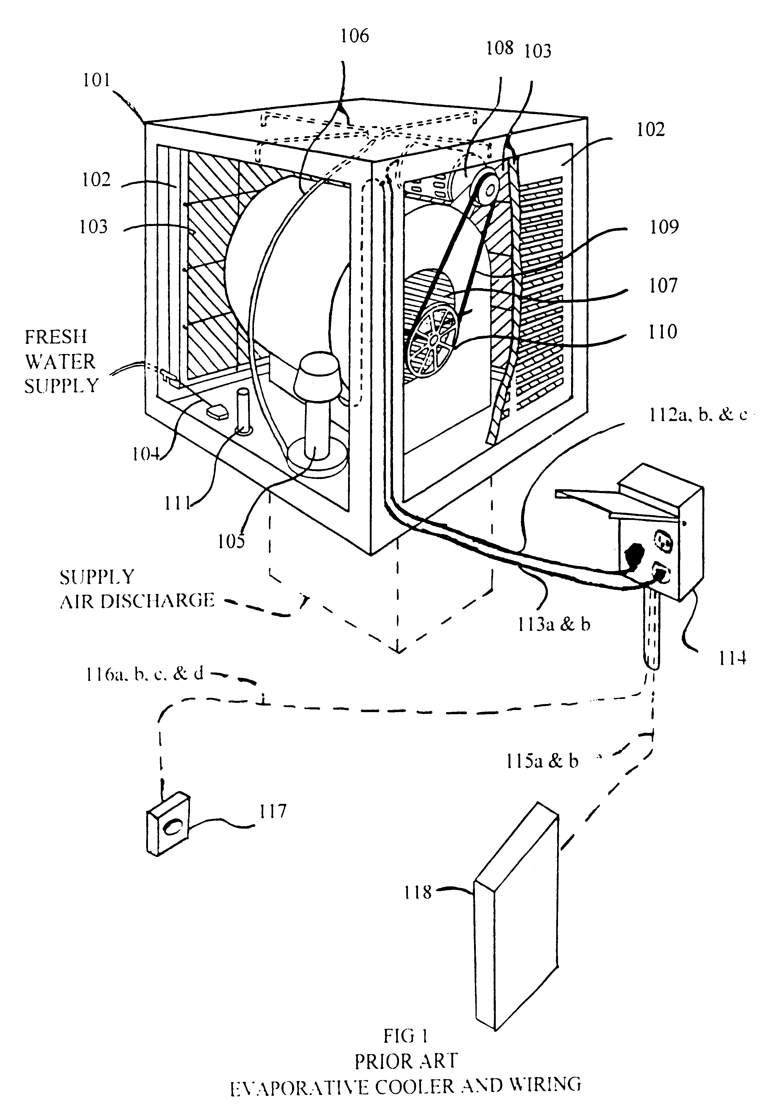
Evaporative Cooler Wiring Diagram Gather the necessary tools and materials. before starting the wiring process, make sure you have all the required tools and materials. this includes a screwdriver, wire strippers, electrical tape, wire nuts, and the evap cooler wiring diagram provided by the manufacturer. 2. turn off the power. Proper installation and wiring are essential for the optimal functioning of the evaporative cooler. the wiring diagram of an evaporative cooler includes various components that work together to ensure efficient cooling. these components include a motor, pump, thermostat, and junction box. the motor powers the fan, while the pump circulates.

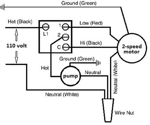
How Does An Evaporative Cooler Swamp Cooler Work Here is how to wire up a 120 volt swamp cooler switch controller. amazon affiliate link to swamp cooler switch: amzn.to 2kx6ludclick here for a comp. The wiring diagram for the evaporative cooler switch typically consists of several components: the power supply, the switch itself, and the motor. the power supply is usually a standard 120 volt electrical outlet, while the switch can be a simple toggle switch or a more advanced thermostat. In conclusion, the proper wiring of evaporative cooler motors is of utmost importance for safety, functionality, and longevity of the cooling system. by ensuring that the wiring is correctly installed and maintained, users can mitigate the risks of electrical hazards, avoid motor failures, and optimize the performance of their evaporative coolers. Example evaporative swamp cooler switch wiring diagram. be sure to always follow the schematics from the manufacturer for any motor or switch. the common (white) wires are usually all tied together in a wire nut. swamp cooler motors can be 1 speed usually labeled only low, and 2 speed usually labeled both low and high.

Mastercool Evaporative Cooler Wiring Diagram In conclusion, the proper wiring of evaporative cooler motors is of utmost importance for safety, functionality, and longevity of the cooling system. by ensuring that the wiring is correctly installed and maintained, users can mitigate the risks of electrical hazards, avoid motor failures, and optimize the performance of their evaporative coolers. Example evaporative swamp cooler switch wiring diagram. be sure to always follow the schematics from the manufacturer for any motor or switch. the common (white) wires are usually all tied together in a wire nut. swamp cooler motors can be 1 speed usually labeled only low, and 2 speed usually labeled both low and high. Once you have roughed in the wiring and water line to the attic, simply pull across them across the attic space to your roof jack next to the cooler. the water line. use 1 4" copper (preferable) or 1 4" plastic tubing. 1 4" pex may also be used, but takes special tools to prepare the joints. The wiring diagram will indicate which wire should be connected to the corresponding terminal. two speed motors: two speed motors offer more flexibility for controlling the speed of the evaporative cooler. these motors typically have three wires, labeled “high,” “medium,” and “low.”. the “high” wire is used for the highest speed.

Evaporative Cooler Wiring Diagram Once you have roughed in the wiring and water line to the attic, simply pull across them across the attic space to your roof jack next to the cooler. the water line. use 1 4" copper (preferable) or 1 4" plastic tubing. 1 4" pex may also be used, but takes special tools to prepare the joints. The wiring diagram will indicate which wire should be connected to the corresponding terminal. two speed motors: two speed motors offer more flexibility for controlling the speed of the evaporative cooler. these motors typically have three wires, labeled “high,” “medium,” and “low.”. the “high” wire is used for the highest speed.

Comments are closed.